When diving into system modeling, there are a few visuals you can’t skip, and one of them is the Sequence Diagram. This diagram is your go-to for defining the sequence of events that need to lead to a specific result. First, you list certain objects and draw vertical dashed lines beneath them, which we call Lifelines—they represent the flow of time. Then, you sketch arrows to show messages being sent across. 📈
A well-crafted diagram can enable even developers unfamiliar with the system to grasp its structure and dependencies, making it easier to get started on projects. However, in large systems, creating diagrams for every function or event can be overwhelming. Back in the day, design and development were often separate tasks, and we used UML (Unified Modeling Language) for clear communication. But these days, Agile methodologies, which emphasize fast-paced collaboration among team members, are in vogue, meaning UML isn’t as commonly used. Still, it’s essential to tailor methodologies based on the project’s needs and context.
Honestly, more than UML or methodologies, I wanted to share how Sequence Diagrams can be incredibly useful when things aren’t flowing smoothly or when a problem needs solving. 🛠️ Usually, when tackling such tasks, developers and collaborators discuss together, but bridging information gaps can be time-consuming. Even the smartest minds can hit roadblocks. That’s when the Sequence Diagram becomes a lifesaver—helping everyone get on the same page and tackle the issue head-on. 🤝
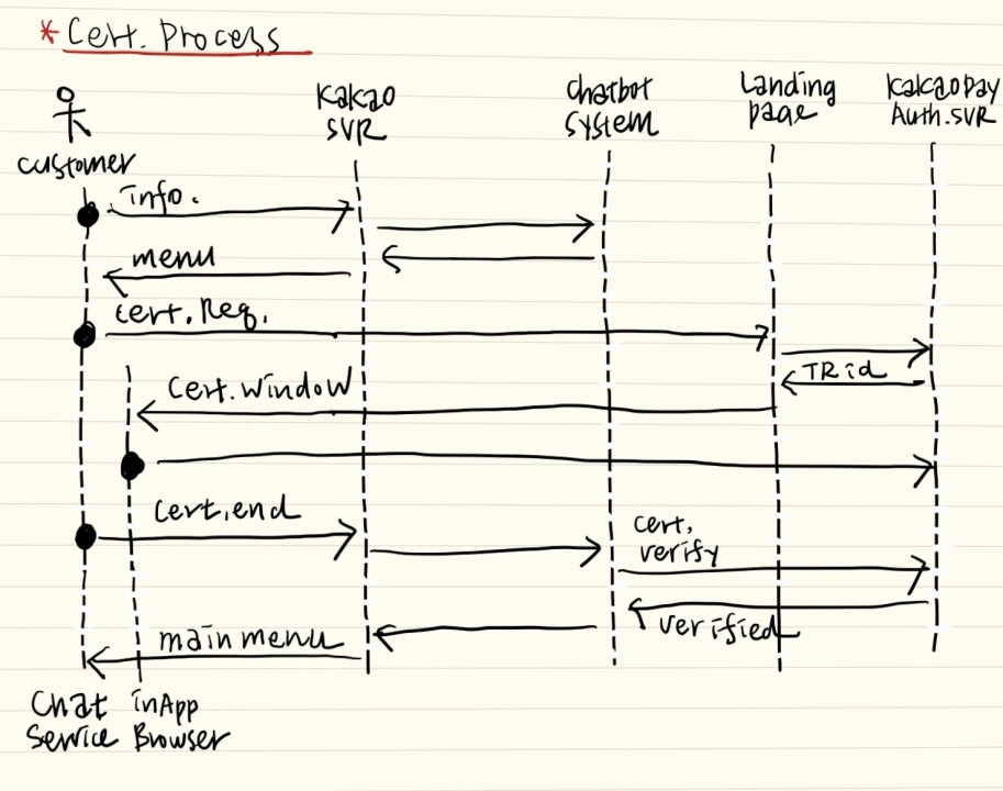
Not long ago, I worked on implementing a feature that used an authentication service from the same company within a chat service platform. We weren’t getting the user experience we desired. While exploring other options with the developer, the complex authentication process made it clear that a surface-level understanding wouldn’t cut it. So, we crafted a Sequence Diagram together. Even developers can sometimes misunderstand the structure, as they rarely handle A to Z alone. As we mapped messages on Lifelines, everything clicked into place. The key is to resolve any ambiguities during the process. Typically, you separate classes (or subsystems) to create distinct Lifelines. For instance, with that authentication service I mentioned earlier, it was crucial to know which subsystem was privy to the authentication info.
Initially, it seemed okay to create a Lifeline for the chat platform used by customers. But as we mapped out message lines between subsystems, we discovered logical issues due to the chat platform’s chat thread area and in-app browser working exclusively. In such cases, it’s better to separate the chat platform into the chat area and in-app browser, each with its own Lifeline, allowing for a more precise structural depiction. (For authentication, knowing which subsystem holds the authentication info is key.)
However, there’s a realm that Sequence Diagrams can’t conquer—finding solutions even when the understanding is clear. Crafting new value within limited structures demands creativity. Sometimes, you might realize, ‘There’s no solution to this problem,’ and that realization in itself can be enlightening, though whether it helps is up for debate…
Leave a Reply